
Tap-operated Switch
Project Description
With this project you will build a circuit based around the 555 timer/oscillator integrated circuit (IC), which alternately turn a light emitting diode (LED) on and off in response to a tap or knock on a piezo electric transducer.
A kit of parts is available from the Bitsbox shop.
Breadboard Layout
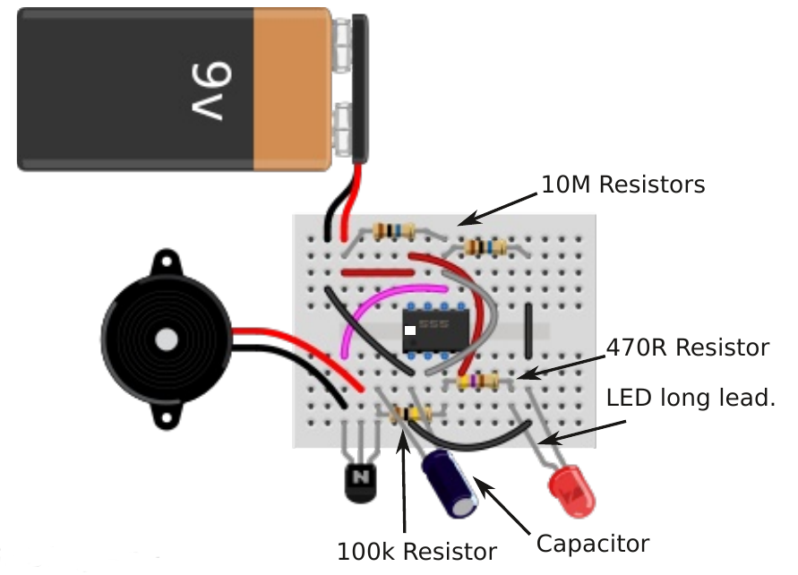
Points to note: Make sure the IC (555 timer), the capacitor, transistor and LED are the correct way round.
Schematic
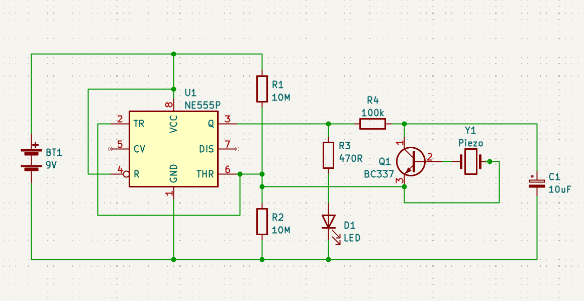
How It Works
The operation relies on two properties of the
555 IC.
1. When the voltage on pin 2 (trigger) drops below 1/3 of the supply voltage, pin 3 (output) switches ON.
2. When the voltage on pin 6 (threshold) rises above 2/3 of the supply voltage, pin 3 switches OFF.
Pins 2 and 6 are connected together and held at 1/2 the supply voltage by resistors R1 & R2.
If the output is ON, a tap on the piezo will activate the transistor raising the voltage on pin 6, turning OFF the output.
If the output is OFF, a tap on the piezo will then apply a negative voltage, which is detected by pin 2 and the output turns ON.