
Dark-Activated LED
Project Description
This circuit automatically turns on an LED when it gets dark (like a nightlight). When there's light, the LED stays off. When it gets dark, the LED turns on.
Breadboard Layout
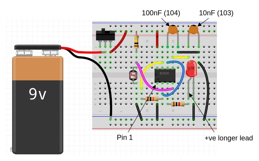
Points to note: Make sure the IC (555 timer) and LED are the correct way round.
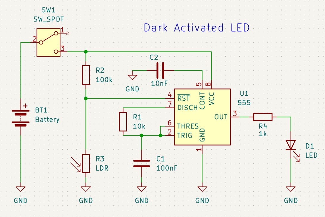
Schematic
How It Works
The Main Components:
LDR (R3) - Light Dependent Resistor: This is the "light sensor".
- In bright light: Acts like a small resistor (low resistance).
- In darkness: Acts like a big resistor (high resistance).
555 Timer (U1): The "brain" of the circuit that decides when to turn the LED on or off.
SW1 Switch: Turns the whole circuit on/off to save battery
LED (D1): The light that turns on in darkness
Step-by-Step Operation:
When there's LIGHT:
- The LDR (light sensor) has low resistance.
- This keeps the voltage at pin 2 (TRIG) HIGH.
- The 555 timer output stays OFF.
- LED remains OFF ✨ (no light needed!).
When it gets DARK:
- The LDR resistance increases (blocks current).
- Voltage at pin 2 (TRIG) drops LOW.
- This triggers the 555 timer.
- The 555 output (pin 3) goes HIGH.
- Current flows through R4 and lights up the LED 💡.
Supporting Components:
- R1 (10k) & R2 (100k): Set the sensitivity threshold.
- C1 (100nF): Smooths out the trigger signal (prevents flickering).
- C2 (10nF): Helps stabilize the 555 timer's internal control voltage.
- R4 (1k): Current-limiting resistor to protect the LED.
Real-World Use:
This is essentially an automatic nightlight circuit. You could use it for:
- Hallway nightlights that turn on automatically at night
- Garden path lights
- Emergency lighting that activates in darkness
- Any application where you want light only when it's dark
The beauty of this circuit is its simplicity - no programming needed, just basic electronic components working together!