Introduction to the Breadboard
What is a Breadboard?
A breadboard (also called a solderless breadboard) is a reusable platform for building and testing electronic circuits without soldering. It's called a "breadboard" because early prototypes were literally built on wooden bread-cutting boards with nails hammered in to them. A modern equivalent is a plastic board, available in a variety of sizes, with a grid of holes. Inside the board are metal spring clips that electrically connect certain holes together. You insert component leads and jumper wires into the holes to build circuits.
Basic Breadboard Layout.
Most breadboards have three main sections:
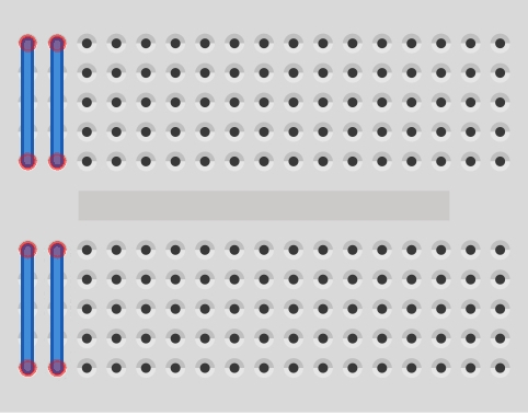
Power Rails - usually located along the long edges, used for distributing power and often marked with red (+) and blue (−) lines.
Terminal Strips (main area) - usually columns of 5 holes connected together. This is where the components are arranged.
Centre Gap - separating the upper and lower strips. Integrated circuits can sit across the gap,

Note: Some breadboards will put a central break in the power rails. This is usually denoted by a break in the red and blue lines. If you don't want to make use of this break simply bridge it will jumper wires.
Mini Breadboard
A Simple Demonstration Circuit:

This simple circuit using a 1k resistor and LED demonstrates using the power rails and terminal strips to make circuit connections.
Following the current path from the +ve of the battery, the red lead is plugged in to the +ve (red) power rail running across the top of the breadboard. The rail carries the current to the top of the resistor which is plugged in to the rail and a vertical terminal strip below. The +ve side of a LED (longer lead) is plugged in to the same terminal strip as the resistor, so becomes electrically connected to it, while the -ve side is plugged in to another terminal strip. A jumper wire bridges the central gap to connect the LED to the lower -ve power rail into which the -ve side of the battery is also plugged. This completes the circuit and the LED will light.
Jumper Wires
Used to make connections between holes.. Ready-made jumpers are available - Bitsbox Jumper Wires - or, to keep things neat and tidy, make your own. Solid-core wire is ideal, 1/0.6mm (22-24 AWG).
Common Beginner Mistakes
Forgetting the centre gap
Shorting power rails
LED polarity reversed
Assuming rows run horizontally in the middle section
Power rails not connected end-to-end