
Adjustable 2-4 Minute Timer
Project Description
This is an adjustable timer circuit - like an egg timer or countdown alarm.
When you press the pushbutton (SW2), the timer starts counting down. The RED LED (LED1) lights up to show the timer is running. When the countdown finishes, the GREEN LED (LED2) turns on to tell you "time's up!"
You can adjust how long the timer runs using the potentiometer (RV1) - twist it to change the delay from roughly 2 to 4 minutes.
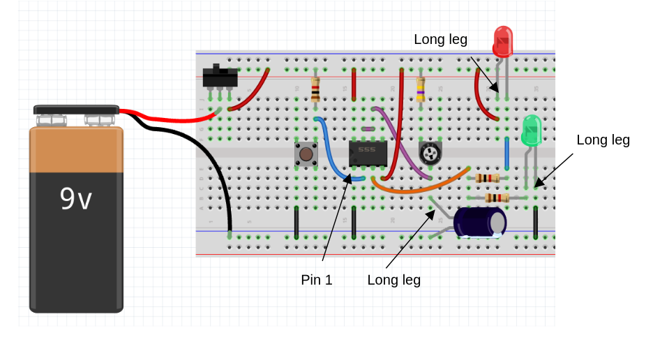
Breadboard Layout
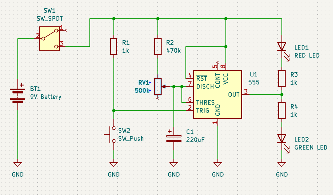
Schematic
How It Works
1. Power On (SW1):
- The SPDT switch (SW1) turns the whole circuit on/off
- When switched to position 2, the 9V battery powers everything
2. Starting the Timer (Press SW2):
- When you press the pushbutton (SW2), it briefly connects pin 2 (TRIG) to ground
- This triggers the 555 timer to start
- The 555's output (pin 3) immediately goes HIGH (turns on)
- RED LED (LED1) lights up through R3 (1kΩ) - showing "timer is running"
3. Timing Period (Waiting):
- Capacitor C1 (220µF) starts charging through resistors R2 (470kΩ) and RV1 (500kΩ potentiometer)
- The time it takes to charge depends on RV1's setting:
- RV1 at minimum: faster charging = shorter timer
- RV1 at maximum: slower charging = longer timer
- During this whole time, the RED LED stays lit
4. Timer Expires (Time's Up!):
- When C1 charges up to 2/3 of the battery voltage, the 555 detects this on pin 6 (THRES)
- The 555's output (pin 3) goes LOW (turns off)
- RED LED (LED1) turns OFF
- GREEN LED (LED2) turns ON through R4 (1kΩ) - showing "timer finished!"
5. Reset for Next Use:
- Press SW2 again to restart the timer
- C1 discharges through pin 7 (DISCH) inside the 555
- Ready for another countdown!
The Components Explained:
- U1 (555 Timer): The "brain" - counts time in monostable (one-shot) mode
- SW1 (SPDT Switch): Main power on/off switch
- SW2 (Pushbutton): Trigger button to start the timer
- RV1 (500kΩ Pot): Adjustable timing control - twist to change duration
- R1 (1kΩ): Pull-up resistor keeps trigger pin stable
- R2 (470kΩ): Works with RV1 to set the timing range
- C1 (220µF): Timing capacitor - charges slowly to create the delay
- R3 & R4 (1kΩ each): Current-limiting resistors for the LEDs
- LED1 (RED): "Timer Running" indicator
- LED2 (GREEN): "Time's Up!" indicator
Timing Calculation:
The timer duration is: T = 1.1 × (R2 + RV1) × C1
- Minimum time (RV1 = 0Ω):
- T = 1.1 × 470kΩ × 220µF ≈ 114 seconds (~2 minutes)
- Maximum time (RV1 = 500kΩ):
- T = 1.1 × 970kΩ × 220µF ≈ 235 seconds (~4 minutes)
So you can adjust the timer from about 2 to 4 minutes by turning the potentiometer.