
Everyone's First Project
In computer programming world, the first program written when learning a new language is "Hello World" - getting the program to simply print the phrase "Hello World" on the screen.
In the electronics world, the "Hello World" equivalent is the flashing LED.
The project described here introduces the 555 timer (one of the most widely used integrated circuits in history), the light emitting diode (LED), resistors and electrolytic capacitors. You will assemble the circuit on a mini-breadboard and it will flash the LED at a frequency around 3Hz (3 times per second).
Parts Used:
Resistors
- 470 Ohms (470R) – Yellow/Violet/Brown/Gold - Bitsbox part.
- 1000 Ohms (1k) – Brown/Black/Red/Gold - Bitsbox part.
- 220,000 Ohms (220k) – Red/Red/Yellow/Gold - Bitsbox part.
Capacitor
1 micro-Farad (1uF) 50V - Bitsbox part.
If you are not familiar with polarised capacitors and the importance of connecting them the right way round you should read my introduction to capacitors.
LED
- 5mm Red LED - Bitsbox part.
As with the capacitor the LED must also be connected the right way round to operate. The longer lead indicates the positive (anode) side.
IC
- 555 timer/oscillator - Bitsbox part.
This is an 8-pin integrated circuit. The pins are number from 1 to 8 in an anti-clockwise direction starting in the top left corner. Look for a notch in the casing at the top edge and/or a dimple adjacent to pin 1.
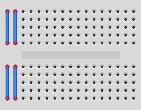
Breadboard
- Mini-breadboard - Bitsbox part.
The Circuit:
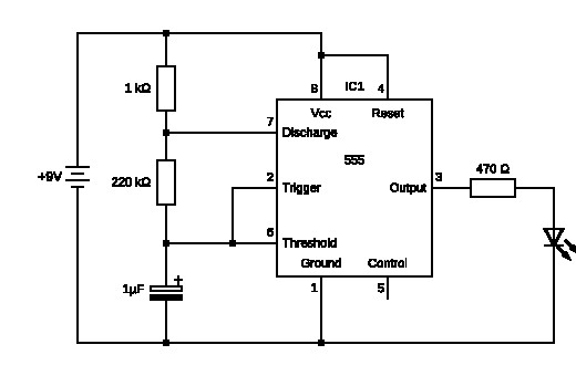
Here's the technical bit.
The 555 is connected in astable mode meaning that its output will switch back and forth between 9V (high) and 0V (low). In this mode it senses the charging of the capacitor to a preset voltage, discharges it, then repeats the cycle, switching the state of the output at each charge and discharge point. The charge and discharge rates, and hence the LED on and off times, are governed by the resistor values - 1k and 220k here.
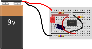
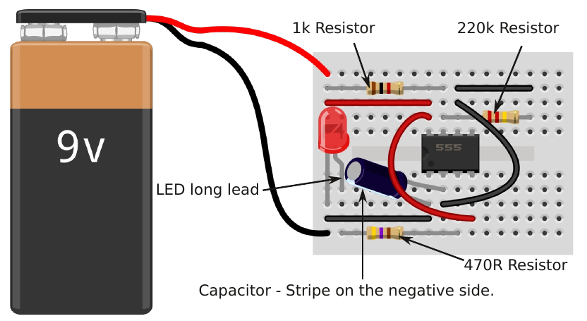
Breadboard Layout:
The parts are plugged in to the breadboard, as shown below. Do not connect the battery until you are happy that all the parts are in the right place and correctly orientated, where necessary. When you connect the battery the LED should flash, but don't be surprised if it doesn't - you will have made a mistake somewhere and that is where the learning starts.
A kit of parts for this project is available from Bitsbox.